One-Stop Sourcing for PLC & HMI Industrial Automation Products | Full Brand Coverage, Hassle-Free Procurement
May 11, 2026
The stable operation of industrial production lines relies heavily on reliable core control components. As the "brain" and "window" of industrial automation, PLCs (Programmable Logic Controllers) and HMIs (Human-Machine Interfaces) directly determine production efficiency, equipment stability, and long-term operation and maintenance costs. For manufacturing enterprises, project engineering parties, and equipment maintenance teams, finding a supplier with a complete product range, guaranteed quality, and professional services can not only save procurement time but also avoid a series of procurement pain points such as incorrect selection, inconsistent quality, and delayed after-sales support, providing strong protection for production and operation.
As a professional supplier deeply engaged in the industrial automation field, we focus on the one-stop supply of core industrial products such as PLCs and HMIs. With our core advantages of "full brand coverage, full product range, and full-service support", we have become the preferred partner for many enterprises in purchasing industrial products. We can also provide precise matching for your procurement needs, helping you reduce procurement costs, improve procurement efficiency, and enjoy a worry-free experience throughout the process.
Full Brand Coverage, Bid Farewell to Multi-Channel Toss, More Efficient Procurement
We deeply understand the pain points of industrial procurement——the market is filled with a wide variety of PLC and HMI brands and models, and different brands are suitable for different working conditions. During procurement, it is often necessary to connect with multiple suppliers, which is not only time-consuming and labor-intensive but also prone to problems such as model mismatch, chaotic pricing, and delayed delivery, seriously affecting project progress and production plans.
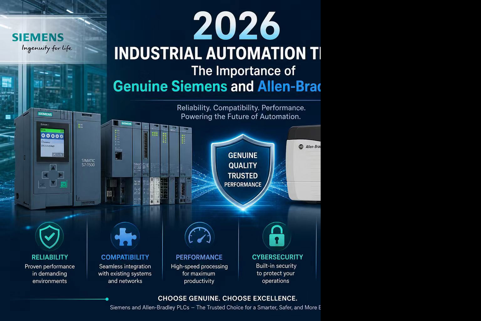
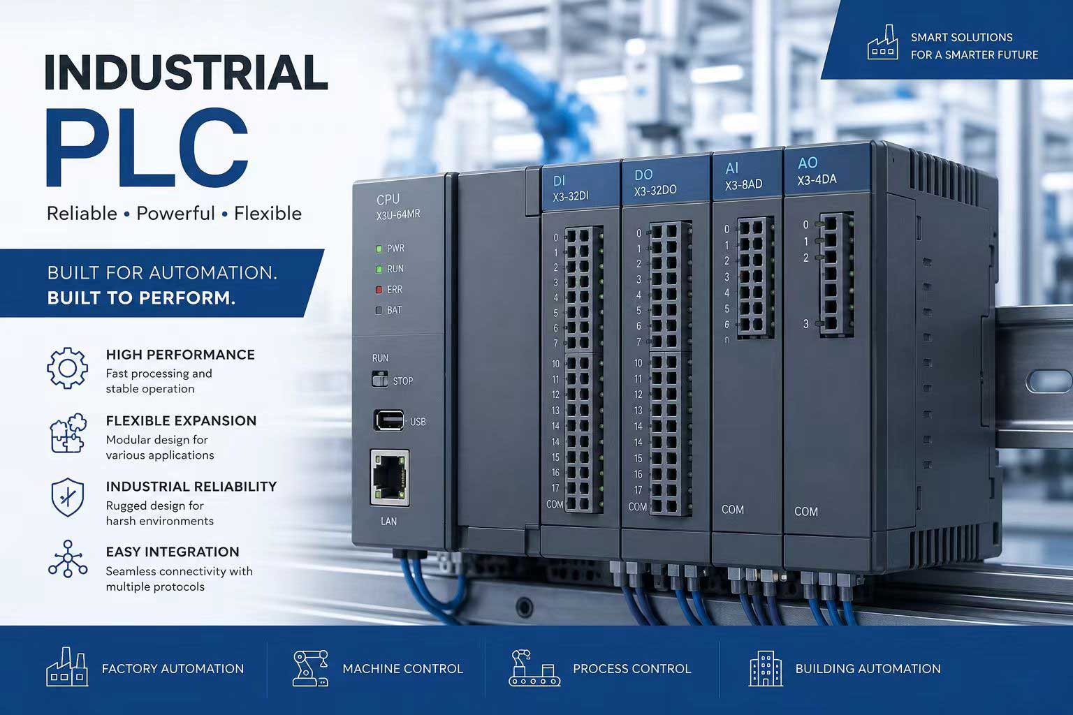
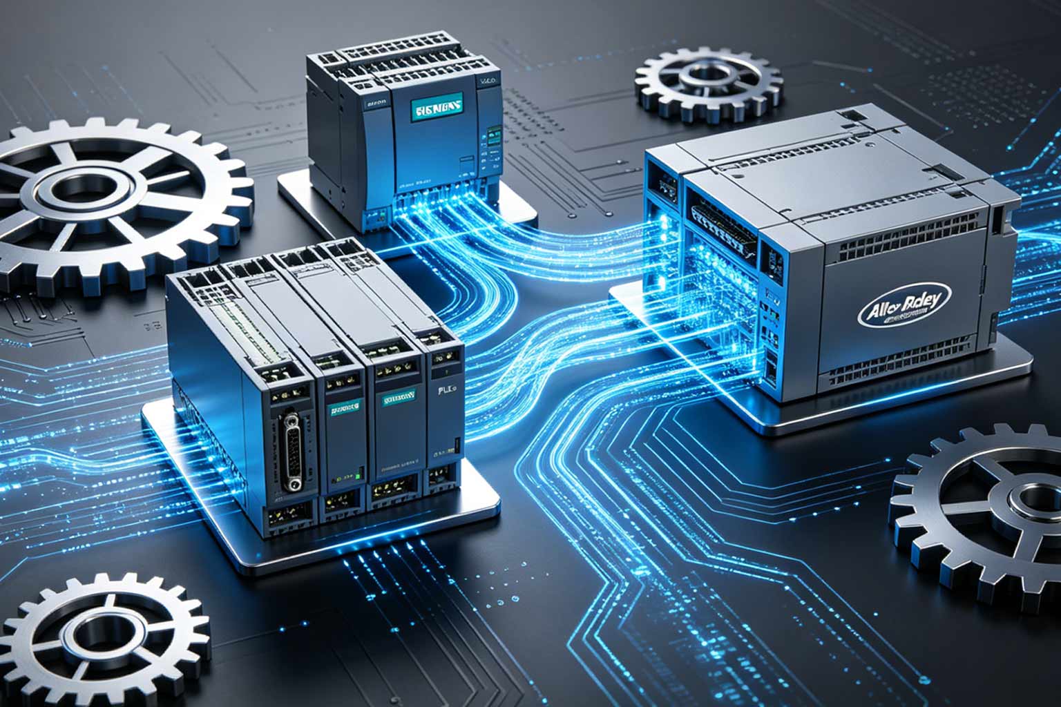
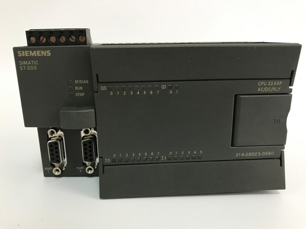
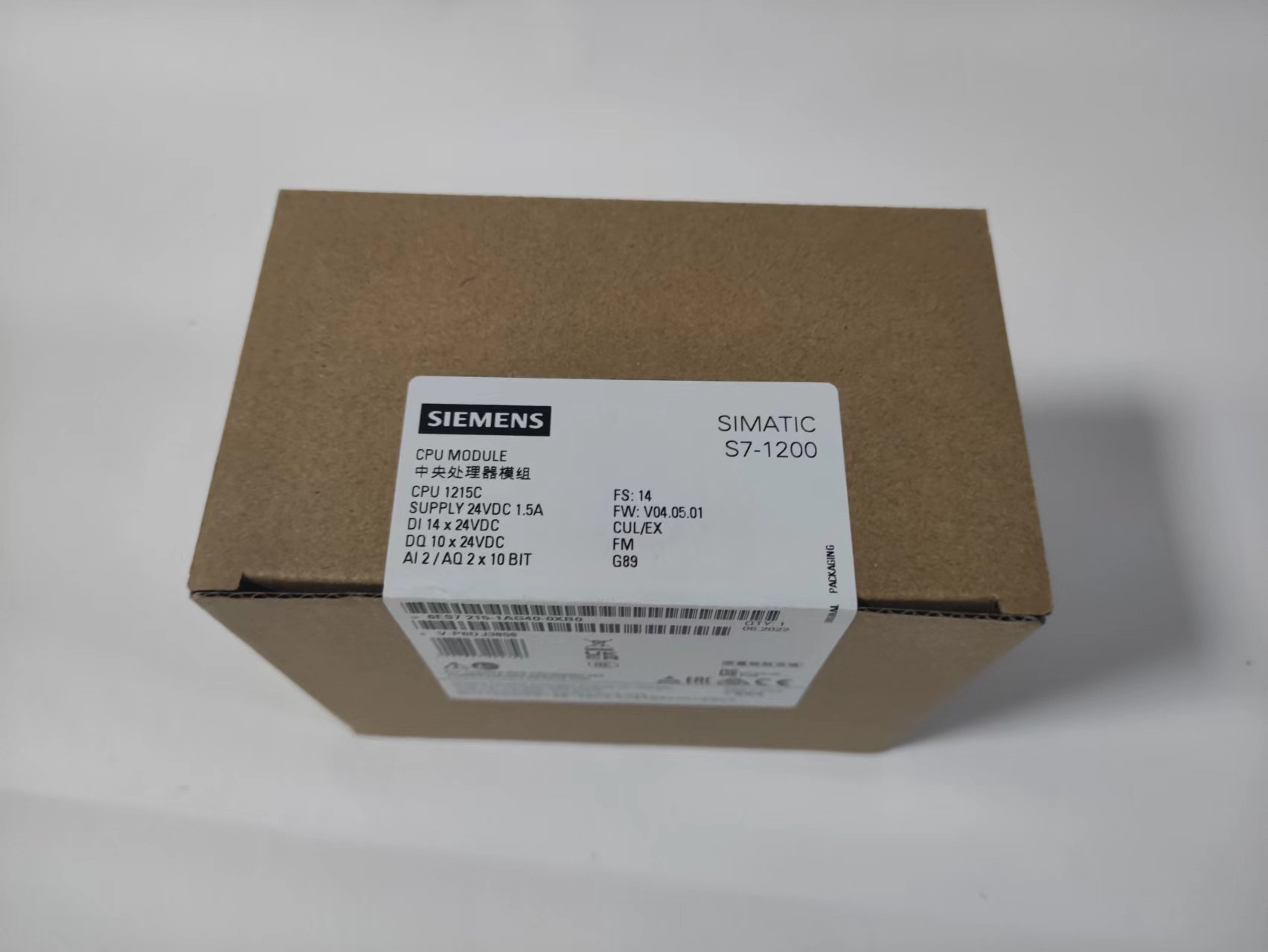
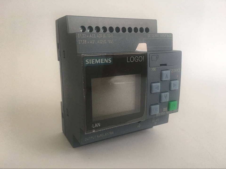
To address this, we have integrated all mainstream and niche brand resources on the market, achieving full coverage of all brands and models of PLC and HMI products, eliminating the need for you to compare prices and connect repeatedly with multiple parties. Whether it is internationally renowned brands such as Siemens, Allen-Bradley, Mitsubishi, Omron, and Schneider, or high-quality domestic brands such as Haiwei and Inovance; whether it is classic PLC main units, HMI touch screens, or supporting peripheral products such as expansion modules, configuration software, and IoT modules, we have spot supply. We can meet all your procurement needs in one stop, completely bid farewell to the trouble of multi-channel tossing, and make procurement more efficient and convenient.
According to different scenario needs, we can also provide precise product selection suggestions——whether it is a cost-effective PLC and HMI combination required for small-scale automation projects, high-performance and high anti-interference control components required for large-scale production lines, intelligent products that support IoT functions and remote access, or durable products suitable for harsh industrial environments, we can recommend the most suitable products for you based on your working condition parameters and budget range, avoiding the selection misunderstanding of "correct parameters but mismatched working conditions" and reducing procurement risks.
Authentic Product Guarantee + Stable Supply, Build a Solid Line of Defense for Production Safety
The quality of industrial products is directly related to the stable operation of production lines. Once counterfeit, refurbished, or inferior products are purchased, it will not only lead to frequent equipment failures and production line shutdowns but also埋下 potential safety hazards and cause incalculable economic losses. This is also one of the core concerns of many enterprises when purchasing industrial products.
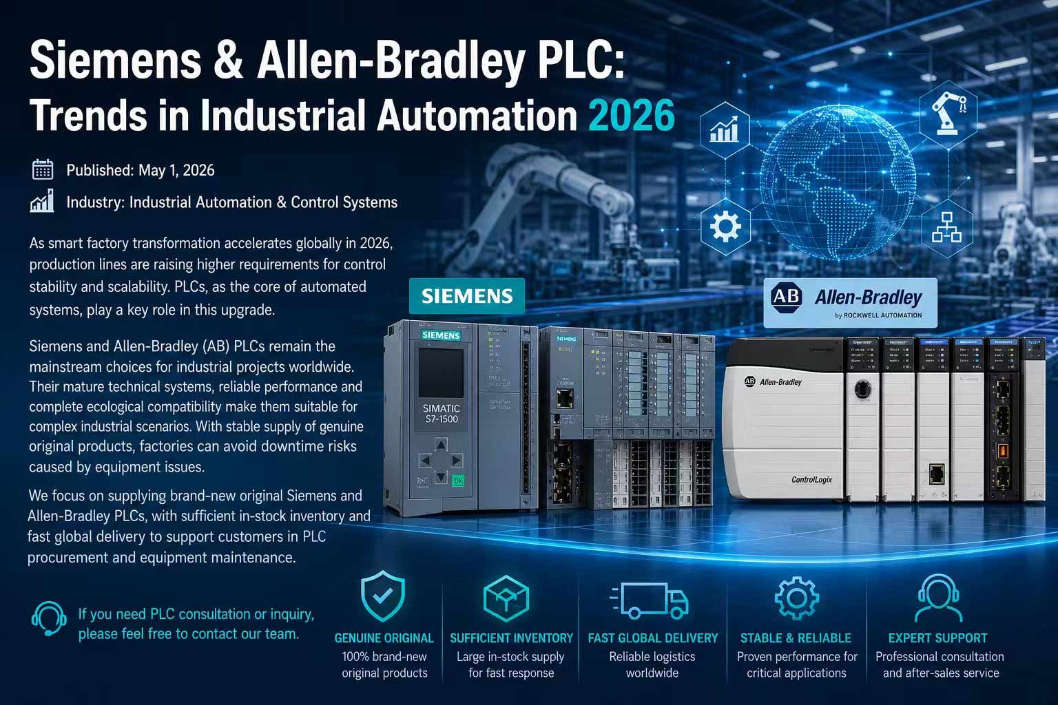
We always put quality first. All PLC and HMI products we supply are brand-new original authentic products, directly connected to brand original factories or core authorized channels, eliminating the flow of counterfeit and refurbished goods into the market. Each product can provide authenticity verification certificates and relevant certification reports, ensuring that product quality meets industrial-grade standards, with strong anti-interference ability, stable operation performance, and long service life, suitable for various complex industrial environments, and building a solid line of defense for your production stability.
At the same time, we have a complete warehousing and logistics system, with year-round spot reserves for conventional models. Emergency orders can be quickly responded to and delivered in a timely manner, avoiding project stagnation or production line shutdowns caused by delayed delivery; for customized needs or scarce models, we can also quickly connect with original factories relying on our strong channel advantages to ensure the supply cycle, so you don’t have to worry about supply issues.
Professional Services + Complete After-Sales Support, Worry-Free Procurement Throughout the Process
Industrial product procurement is never just "buying products", but also requires professional technical support and complete after-sales services. We have an experienced industrial automation technical team. Whether it is pre-product selection, parameter confirmation, mid-term installation and commissioning guidance, or later fault diagnosis and maintenance, we can provide one-on-one professional services, promptly solve various problems you encounter in the process of product use, help you quickly get started with the products, and reduce operation and maintenance costs.
According to the characteristics of PLC and HMI products, we also provide comprehensive after-sales guarantee, clarifying the scope and period of quality assurance. When there is a quality problem with the product, we will respond quickly and handle it in a timely manner. Whether it is product replacement or maintenance and debugging, we can promote it efficiently to minimize your losses; at the same time, we also provide long-term technical consulting services to help your equipment achieve optimization and upgrading, adapt to the future needs of factory expansion, and realize cost reduction and efficiency improvement.
Why Choose Us? —— 3 Core Advantages, Addressing Procurement Pain Points Directly
Hassle-Free: Full brand and product coverage, one-stop procurement, no need for multi-party connection, saving your procurement time and labor costs;
Assured: Brand-new original authentic product guarantee, traceable quality, stable supply, eliminating procurement risks and hidden costs;
Considerate: One-on-one professional product selection guidance + complete after-sales guarantee, providing technical support throughout the process, worry-free from procurement to use.
Whether you need to purchase PLC and HMI products in bulk for project construction, or purchase spare parts in small quantities for equipment maintenance; whether you value brand reputation, product quality, or pay attention to supply efficiency and after-sales guarantee, we can meet your needs. With professionalism and integrity, we will become your long-term trusted industrial product procurement partner.
Consult now to get exclusive procurement quotes and product selection suggestions, as well as exclusive procurement discounts! If you have procurement needs for PLC, HMI and other industrial products, please contact our team, tell us your working conditions, budget and needs, and we will provide you with a precisely matched procurement plan to help you reduce procurement costs, improve production efficiency, and make industrial procurement more worry-free and efficient!
【Inquiry Guide】To learn about specific product models, quotes, or obtain professional product selection suggestions, you can directly leave a message on the website, consult online, or contact our customer service team. We will respond to you as soon as possible and serve you wholeheartedly!


 IPv6 network supported