banner
  • Siemens S7-1200 Practical Troubleshooting Guide | Hardware Selection, Programming, Communication & On-site Tips
    Siemens S7-1200 Practical Troubleshooting Guide | Hardware Selection, Programming, Communication & On-site Tips Jun 19, 2026
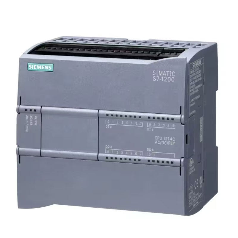
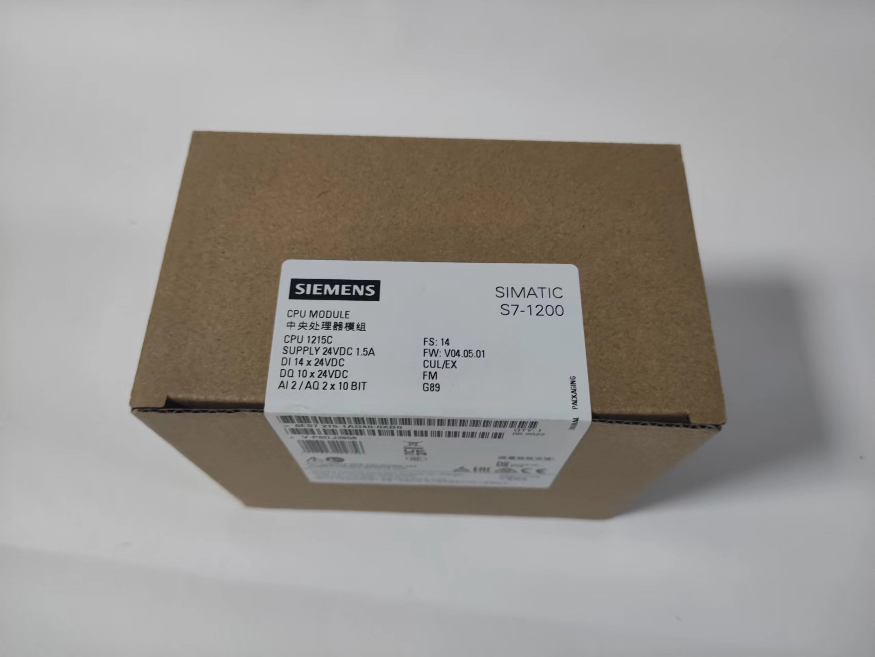
      Introduction Most automation engineers and equipment buyers only master basic programming operations of the Siemens S7-1200 PLC, but frequently encounter various on-site issues: failed PLC connection after equipment arrival, servo jitter, unstable analog data, random fault shutdowns, and program download failures. In most cases, these problems are not caused by hardware damage, but by improper selection, non-standard wiring, incorrect parameter settings, and bad programming habits. This blog focuses entirely on practical, problem-solving skills and high-frequency pitfalls for end users and field engineers. No empty theoretical parameters—all solutions can be applied directly to fix 90% of common S7-1200 faults, stabilize equipment operation, and reduce after-sales costs. 1. Critical Selection Mistakes | Avoid Rework & Financial Loss 1.1 Wrong CPU Power Version = Failed Motion Control Many beginners select PLC models randomly without distinguishing version differences, resulting in unavailable high-speed positioning and servo control after installation. DC/DC/DC Version (Industrial Standard & Preferred) 24V DC power supply, transistor output Supports 100kHz high-speed pulse output, directly drives servo and stepper motors Ideal for all positioning, cutting, reciprocating motion automation equipment AC/DC/RLY Version (Only for Simple On/Off Control) 220V AC power supply, relay output No high-speed pulse function, cannot realize any positioning control Only applicable to fans, water pumps, lighting, and simple start-stop devices Key Rule: Choose DC/DC/DC unconditionally if your device involves servo, stepper, or positioning functions! 1.2 Insufficient CPU Performance Margin | Stuttering & Pulse Loss Field-verified S7-1200 selection standards for industrial projects: Simple logic & ordinary IO devices: 1212C ≤4-axis servo, packaging & conveying equipment: 1214C (Most Popular Universal Model) Multiple analog signals, PID control & multi-device networking: 1215C High-precision positioning, cutting & multi-axis synchronization: 1217C Practical Tip: Keep program memory usage below 70% and OB1 cycle time within 100ms. Exceeding these values will easily cause packet loss, program stuttering, and random equipment shutdowns. 1.3 Disordered Expansion Module Installation | Module Recognition Failure S7-1200 has strict expansion slot rules. All expansion modules must be installed sequentially from the first slot on the right of the CPU. Empty slots or disordered installation will trigger faults and make modules unrecognizable. Optimal Layout Skill: Keep communication and power modules away from high-temperature modules to avoid high-temperature crash faults; place digital output modules on the rightmost side to reduce signal interference. 2. Hardware Wiring & Installation Tips | Eliminate Interference & False Triggering 2.1 Unstable Analog Data & Signal Drift | Permanent Solution Common on-site fault: Temperature, pressure and flow data jitter continuously, even with intact sensors and correct programs. Solutions: Use shielded cables for analog signals with single-end grounding Separate power cables (servo/inverter cables) from signal cables with a distance of more than 20cm; never lay them in the same pipe Enable analog filtering and smooth sampling in TIA Portal to eliminate data drift completely 2.2 Digital Input False Triggering & Random Light Flashing Many users encounter random flickering of PLC input indicators during equipment shutdown. Cause: Power frequency interference and induced voltage of long signal cables Solution: Adjust DI input delay to 3ms~5ms in TIA Portal hardware configuration to eliminate false triggering thoroughly with low cost. 2.5 Random Restarts & Faults Caused by Unstable Power Supply S7-1200 CPUs are sensitive to power ripple. Low-quality switching power supplies will cause random disconnection, program loss and module errors. Recommendation: Adopt industrial regulated power supplies, and install anti-interference magnetic rings at the CPU power terminal to greatly improve equipment stability. 3. Programming Practical Skills | Stable, Maintainable & Bug-Free Programs 3.1 Avoid Abusing Memory Bits (M Bits) to Prevent Hidden Faults Novice engineers often use M0.0, M0.1 and other M bits for intermediate logic, which leads to variable conflicts and logic disorder after long-term equipment operation. Best Practice: Prioritize DB data blocks for S7-1200 programming. Independently allocate variables for equipment actions, alarms and statuses to ensure clear logic, no conflicts and easy maintenance. 3.2 Timer Pitfall | Avoid Timing Deviation & Logic Drift Common fault: Inaccurate timing and drifting cycle logic during long-term operation. Avoidance Rule: Do not mix TON and TOF timers for cyclic oscillation logic. Uniformly adopt IEC timers for stable resolution and zero cumulative time error. 3.3 Add Fault Tolerance for Analog Programs | Prevent Equipment Crash Sensor disconnection and poor contact will cause program crash, PID out-of-control and misoperation without fault tolerance logic. Universal Fault Tolerance Method: Set upper and lower limit judgment for analog data. Lock outputs and trigger alarms when values exceed the normal range to avoid over-temperature and over-pressure risks. 3.4 Ultimate Solution for Axis Homing Faults High-frequency problem: The axis stops with an alarm when hitting the limit switch during homing, without automatic reverse reset. Solutions: Enable the "limit switch automatic reverse" function in hardware configuration Properly increase acceleration and deceleration time to avoid hard collision with limits Reserve a safe distance between limit switches and mechanical stops 4. Communication Troubleshooting | Fix Connection Failure & Random Disconnection 4.1 PLC Not Found & Failed PC Connection 90% of connection failures are network problems rather than hardware damage: Default PLC IP: 192.168.0.1, easy to conflict with local LAN IP segments Set a static IP address for the PC network adapter (same segment as PLC), disable automatic IP acquisition Turn off PC firewall and antivirus software to prevent communication interception 4.2 Random Disconnection of PROFINET & HMI Core Skill: Use PROFINET instead of Modbus for multi-device networking. Properly extend the communication timeout, and adopt industrial shielded Ethernet cables to eliminate on-site interference disconnection. 4.3 Program Download Failure Caused by Firmware Version Mismatch High-frequency pitfall: Programs compiled with high-version TIA Portal cannot be downloaded to low-version firmware PLCs. Solution: Check the PLC firmware version before downloading, match the hardware version in TIA Portal, or upgrade the firmware online to unify versions. 5. On-Site Fast Troubleshooting Skills | After-Sales Efficiency Tool 5.1 Diagnose via Diagnostic Buffer (Fastest Fault Location) S7-1200 is equipped with a powerful built-in diagnosis system, recording the exact time and cause of all shutdowns and module faults. Enter online mode in TIA Portal and check the diagnostic buffer to locate faults accurately, avoiding blind line and program inspection. 5.2 Random Shutdown Without Alarm Prompt Main causes: Excessive program cycle time, high memory occupancy, and electromagnetic interference. Solutions: Simplify program logic, reduce OB1 cycle time, optimize wiring layout, and add anti-interference measures. 6. Daily Maintenance & Lifespan Extension Tips Regularly clean dust from the PLC heat dissipation channel to avoid high-temperature frequency reduction and crash faults Install a memory card for key projects and back up programs regularly to prevent program loss Check the power supply voltage before powering on long-term shutdown equipment to avoid CPU damage from voltage surge Never hot-swap signal modules to prevent port burnout Summary The Siemens S7-1200 PLC features excellent inherent stability. 90% of on-site faults are caused by wrong selection, non-standard wiring, missing parameter settings and lack of program fault tolerance. Mastering the above practical skills can help you avoid procurement pitfalls, completely solve common problems such as analog jitter, communication disconnection, positioning faults and random shutdowns, greatly reduce after-sales pressure, and improve overall equipment stability. Interaction: What tricky S7-1200 faults have you encountered on-site? Leave a comment to share your troubleshooting experience!
  • Siemens PLC advantage
    Siemens PLC advantage Nov 03, 2023
    Reliable folding PLC does not require a large number of active components and connected electronic components. Its connections are greatly reduced. At the same time, the maintenance of the system is simple and the maintenance time is short. Plc adopts a series of reliability design methods for design. For example, redundant design. Power outage protection, fault diagnosis, information protection and recovery. PLC is a control device specially designed for industrial production process control, which has a simpler programming language and more reliable hardware than general computer control. Adopting a refined and simplified programming language. The programming error rate is greatly reduced. Easy to fold and operate PLC has high operability. It has the characteristics of simple programming, convenient operation, and easy maintenance, and is generally less prone to operational errors. The operation of PLC includes program input and program change operations. The input of the program can be directly displayed, and the operation of changing the program can also be directly searched or searched by the program based on the required address number or contact number, and then changed. PLC has multiple programming languages available for use. Used for ladder diagrams that are closer to electrical schematics. Easy to grasp and understand. The self-diagnosis function of PLC reduces the requirements for maintenance skills of maintenance personnel. When a system malfunction occurs, maintenance personnel can quickly locate the location of the malfunction through self diagnosis of hardware and software. Flexible folding The programming languages used by PLC include ladder diagram, Boolean mnemonic, function diagram, function module, and statement description programming language. The diversity of programming methods makes programming simple and expands its application scope. The operation is very flexible and convenient, and it is very easy to monitor and control variables. Siemens PLC S7-300 series PLC installation and precautions: 1、 The auxiliary power supply has low power and can only drive low-power equipment (such as photoelectric sensors); 2、 Generally, PLCs have a certain number of occupied points (i.e. empty address wiring terminals), do not connect the wires; 3、 PLC has the issue of I/O response delay, especially in fast response equipment, which should be paid attention to. 4、 There are relay type and transistor type outputs (suitable for high-speed output), and the output can directly carry light loads (LED indicator lights, etc.); 5、 The input/disconnection time should be greater than the PLC scanning time; 6、 There is no protection in the PLC output circuit, so protective devices such as fuses should be used in series in external circuits to prevent damage to the PLC caused by load short circuits; 7、 Do not connect the AC power cord to the input terminal to avoid burning out the PLC; 8、 The grounding terminal should be independently grounded and not connected in series with other equipment grounding terminals. The cutting surface of the grounding wire should not be less than 2mm2; 9、 The input and output signal lines should be routed separately as much as possible, and should not be in the same pipeline or bundled together with the power line to avoid interference signals and misoperation; The signal transmission line adopts shielded wire and the shielded wire is grounded; To ensure signal reliability, the input and output lines are generally controlled within 20 meters; Expansion cables are susceptible to noise and electrical interference, and should be kept away from power lines, high-voltage equipment, etc.
  • Siemens PLC Operational Principle
    Siemens PLC Operational Principle Jun 13, 2023
    operational principle   After the PLC is put into operation, its working process is generally divided into three stages, namely input sampling, user program execution, and output refresh. Completing the above three stages is called a scanning cycle. During the entire operation period, the CPU of the PLC repeatedly executes the above three stages at a certain scanning speed.       Collapse input sampling   In the input sampling stage, the PLC sequentially reads in all input states and data in a scanning manner, and stores them in the corresponding units in the I/O image area. After the input sampling is completed, it enters the user program execution and output refresh phase. In these two stages, even if the input state and data change, the state and data of the corresponding units in the I/O image area will not change. Therefore, if the input is a pulse signal, the width of the pulse signal must be greater than one scanning cycle to ensure that the input can be read in any case.       Collapse User Program Execution   During the execution phase of the user program, the PLC always scans the user program (ladder diagram) in a top-down order. When scanning each ladder diagram, always scan the control circuit composed of each contact on the left side of the ladder diagram first, and perform logical operations on the control circuit composed of the contacts in the order of left to right, top to bottom. Then, based on the results of the logical operations, refresh the corresponding bit status of the logical coil in the system RAM storage area; Or refresh the state of the corresponding bit of the output coil in the I/O image area; Or determine whether to execute the special functional instructions specified in the ladder diagram.       That is, during the execution of the user program, only the state and data of the input points in the I/O image area will not change, while the state and data of other output points and software devices in the I/O image area or system RAM storage area may change. Moreover, the program execution results of the ladder diagram listed above will affect the ladder diagram below that uses these coils or data; On the contrary, in the ladder diagram below, the status or data of the refreshed logic coil can only be applied to the program above it in the next scanning cycle.       Collapse Output Refresh   After scanning the user program, the PLC enters the output refresh stage. During this period, the CPU refreshes all output latch circuits according to the corresponding state and data in the I/O image area, and then drives the corresponding peripheral devices through the output circuit. At this point, it is the true output of the PLC.       The same number of ladder diagrams, with different order of arrangement, result in different execution results. In addition, there are differences between the results of scanning user programs and the results of hard logic parallel operation of relay control devices. Of course, if the time occupied by the scanning cycle can be ignored for the entire run, then there is no difference between the two.
  • Siemens PLC Classification
    Siemens PLC Classification Jun 08, 2023
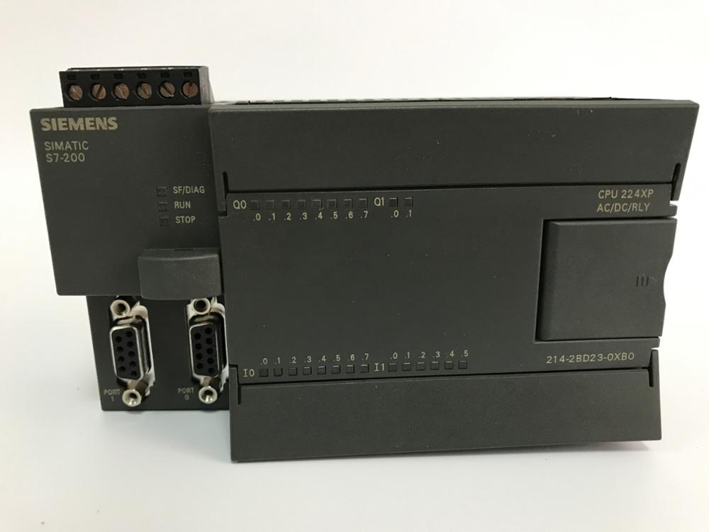
    Programmable controllers are generated by the needs of modern production, and the classification of programmable controllers must also meet the needs of modern production. Generally speaking, programmable controllers can be classified from three perspectives. One is to classify based on the control scale of programmable controllers, the second is to classify based on the performance level of programmable controllers, and the third is to classify based on the structural characteristics of programmable controllers. Folding control scale It can be divided into mainframe, mid size, and small size machines. Mini computer: The control points of a mini computer are generally within 256 points, suitable for single machine control or small system control. Siemens mini machines have S7-200: processing speed of 0.8~1.2ms; Memory 2k; 248 digital points; Analog quantity 35 channels. Medium size machine: The control points of a medium size machine are generally not greater than 2048 points, which can be used for direct control of equipment and monitoring of multiple lower level programmable controllers. It is suitable for medium or large control systems. Siemens mid size machines have S7-300: processing speed of 0.8~1.2ms; Memory 2k; 1024 digital points; Analog quantity 128 channels; Network PROFIBUS; Industrial Ethernet; MPI. Mainframe: The control point of a mainframe is generally greater than 2048 points, which can not only complete complex arithmetic operations but also perform complex matrix operations. It can not only be used for direct control of devices, but also for monitoring multiple lower level programmable controllers. Siemens mainframes have S7-1500 and S7-400: processing speed of 0.3ms/1k words; Memory 512k; I/O point 12672; Folding control performance It can be divided into high-end machines, mid-range machines, and low-end machines. Low-end machine This type of programmable controller has basic control functions and general computing power. The working speed is relatively low, and the number of input and output modules that can be carried is relatively small. For example, the S7-200 produced by SIEMENS in Germany belongs to this category. Mid range machine This type of programmable controller has strong control functions and computing power. It can not only complete general logic operations, but also complete more complex Trigonometric functions, exponent and PID operations. The working speed is relatively fast, and the number of input and output modules that can be carried is also quite large, and there are also many types of input and output modules. For example, the S7-300 produced by SIEMENS in Germany belongs to this category. High end machine This type of programmable controller has powerful control functions and computing power. It can not only perform logic operation, Trigonometric functions operation, exponential operation and PID operation, but also perform complex matrix operation. The working speed is very fast, and there are a large number of input and output modules that can be carried. The types of input and output modules are also very comprehensive. This type of programmable controller can complete large-scale control tasks. Generally used as the main station in networking. For example, the S7-400 produced by SIEMENS in Germany belongs to this category.   Folding structure Integral The integrated programmable controller integrates the power supply, CPU, memory, and I/O system into one unit, which is called the basic unit. A basic unit is a complete PLC. When the control points do not meet the requirements, an expansion unit can be connected again. The characteristics of the integrated structure are very compact, small size, low cost, and convenient installation. Combined A modular programmable controller divides the various components of a PLC system into several modules according to their functions, such as CPU module, input module, output module, power module, and so on. The functions of each module are relatively simple, but the types of modules are increasingly rich. For example, some programmable controllers, in addition to basic I/O modules, also have some special functional modules, such as temperature detection module, position detection module, PID control module, communication module, and so on. The characteristic of a modular PLC is that the CPU, input, and output are all independent modules. Unified module size, neat installation, free selection of I/O points, convenient installation, debugging, expansion, and maintenance. Stacked type The stacked structure combines the advantages of compact, small size, and easy installation of the overall structure, as well as the flexible and neat installation of the I/O points in the combined structure. It is also composed of combinations of various units. Its characteristic is that the CPU is an independent basic unit (composed of the CPU and certain I/O points), and other I/O modules are expansion units. During installation, there is no need for a substrate, only cables are used for connection between units, and each unit can be stacked one by one. Enable the system to achieve flexible configuration and compact size.   Detailed introduction 1. SIMATIC S7-200 PLC S7-200 PLC is a miniaturized PLC that is suitable for automatic detection, monitoring, and control in various industries and occasions. The powerful functions of the S7-200 PLC enable it to achieve complex control functions whether running alone or connected to a network. The S7-200 PLC can provide 4 different basic models and 8 types of CPUs to choose from. 2. SIMATIC S7-300 PLC S7-300 is a modular small PLC system that can meet medium performance requirements for applications. Various individual The modules can be widely combined to form systems with different requirements. Compared with the S7-200 PLC, the S7-300 PLC adopts a modular structure and has high speed (0.6~0.1 μ s) Command operation speed of; Floating-point arithmetic arithmetic can effectively realize more complex arithmetic operations; A software tool with a standard user interface that allows users to easily assign parameters to all modules; Convenient human-machine interface services have been integrated into the S7-300 operating system, greatly reducing the programming requirements for human-machine dialogue. The SIMATIC Human Machine Interface (HMI) obtains data from the S7-300, which transmits it at a user specified refresh rate. The S7-300 operating system automatically handles data transmission; The intelligent diagnostic system of CPU continuously monitors whether the system functions normally, records errors and special system events (such as timeout, module replacement, etc.); Multi level password protection can enable users to highly and effectively protect their technical secrets, preventing unauthorized copying and modification; The S7-300 PLC is equipped with an operation mode selection switch, which can be removed like a key. When the key is removed, the operation mode cannot be changed, which can prevent illegal deletion or rewriting of user programs. Equipped with powerful communication functions, the S7-300 PLC can provide communication configuration functions through the user interface of the programming software Step 7, making configuration very easy and simple. S7-300 PLC has a variety of different communication interfaces, and connects AS-I bus interface and Industrial Ethernet bus system through a variety of communication processors; The serial communication processor is used to connect point-to-point communication systems; Multi Point Interface (MPI) is integrated into the CPU and used to simultaneously connect programmers, PCs, human-machine interface systems, and other SIMATIC S7/M7/C7 automation control systems. 3. SIMATIC S7-400 PLC S7-400 PLC is a programmable controller used in the medium to high performance range. The S7-400 PLC adopts a modular fanless design, which is reliable and durable. At the same time, it can choose multiple levels of CPUs (with gradually upgraded functions) and is equipped with templates for various universal functions, allowing users to combine them into different specialized systems according to their needs. When the scale of the control system is expanded or upgraded, as long as some templates are added appropriately, the system can be upgraded and fully meet the needs.

  • Siemens PLC History
    Siemens PLC History Jun 07, 2023
    The Siemens SIMATIC series PLC was born in 1958 and has gone through the C3, S3, S5, and S7 series, becoming a widely used programmable controller.   1. Siemens' product was first launched in 1975 as the SIMATIC S3, which is actually a binary controller with a simple operating interface.   2. In 1979, the S3 system was replaced by the SIMATIC S5, which widely used microprocessors.   3. In the early 1980s, the S5 system was further upgraded - the U-series PLC, with commonly used models including S5-90U, 95U, 100U, 115U, 135U, and 155U.   4. In April 1994, the S7 series was born, which has advantages such as more internationalization, higher performance level, smaller installation space, and better Windows user interface. Its models are: S7-200, 300, 400.   5. In 1996, Siemens proposed the concept of PCS7 (Process Control System 7) in the field of process control, integrating its advantages of WINCC (Windows compatible operating interface), PROFIBUS (industrial fieldbus), COROS (monitoring system), SINEC (Siemens industrial network), and control technology.   6. Siemens proposed the concept of TIA (Total Integrated Automation), which is a fully integrated automation system that integrates PLC technology into all automation fields.   The S3 and S5 series PLCs have gradually withdrawn from the market and ceased production. The S7 series PLCs have developed into the control core of Siemens automation systems, while the TDC system continues to use the SIMADYN D technology core, which is a further upgrade to the S7 series products. It is the most cutting-edge and powerful programmable controller in Siemens automation systems.

Need Help? Chat with us

leave a message
For any request of information or technical support, fill in the form. All fields marked with an asterisk* are required.
Submit
Looking for Service?
Contact us #
+86 17620189681

Our hours

Mon 11/21 - Wed 11/23: 9 AM - 8 PM
Thu 11/24: closed - Happy Thanksgiving!
Fri 11/25: 8 AM - 10 PM
Sat 11/26 - Sun 11/27: 10 AM - 9 PM
(all hours are Eastern Time)      

home

products

whatsApp

Contact Us